Flight Control Software
ACS software, propulsion control modes, GUI, and communications integration.
Controls and Communications
The communications architecture consists of the on-board Arduino, an ESP32, and the command center/computer.
Controls are sent by the user from the Simulink GUI. Internal calculations are performed based on the control mode, and the data (packaged to control the mass balancers, reaction wheels, and thruster solenoids) is sent to the ESP32 over Wi-Fi.
The ESP32 receives the data, reads and processes it to send to the Arduino.
The Arduino directly handles the mass balancing and solenoid outputs when receiving the ESP32 data. Additionally, it contains a built-in IMU with accelerometer, gyroscope, and magnetometer data. This sensor data is transmitted to the ESP32 and command center.
The data is received and sent by the flight software:
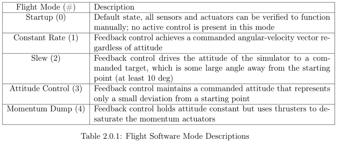
Flight Software
The ACS is operated with MATLAB scripts and a main Simulink model.
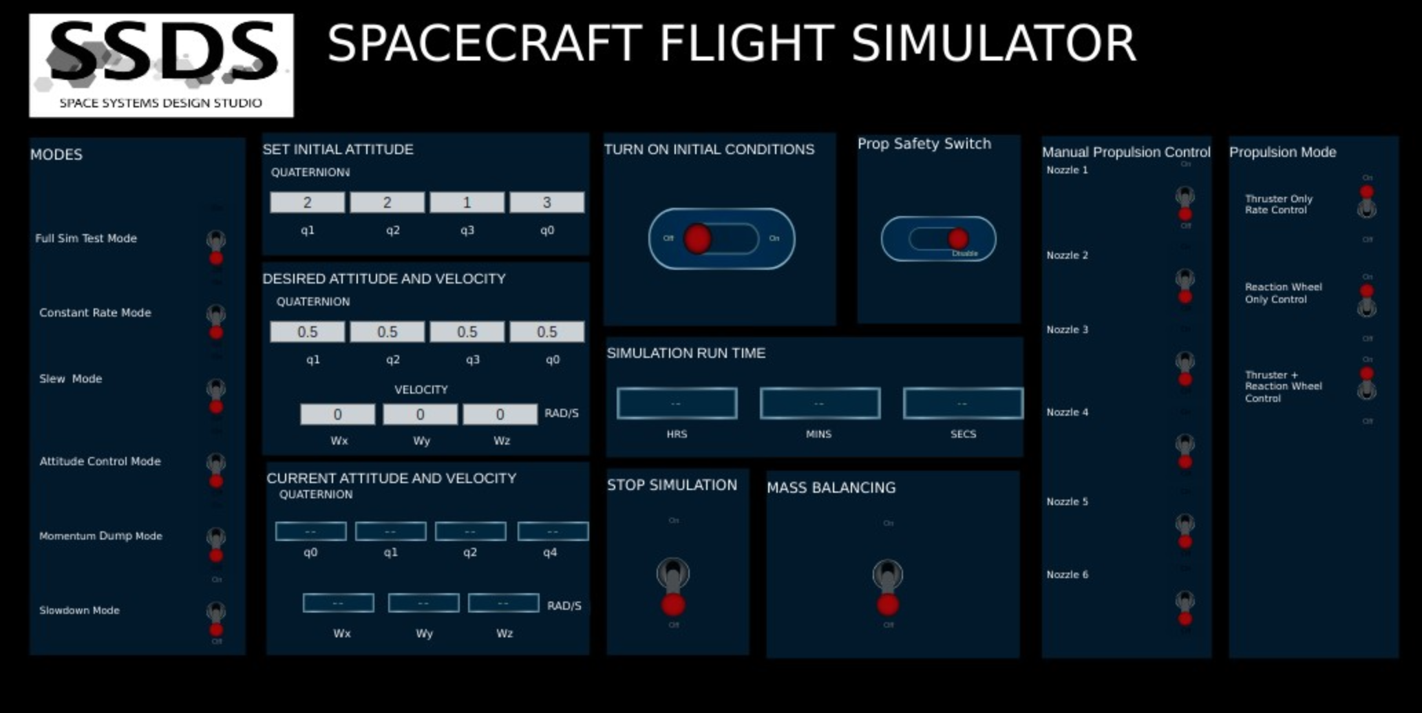
Through the GUI, the control mode is set, the initial conditions are set, and the desired attitude and velocity are input. There are safety switches to turn the simulation or propulsion systems off.
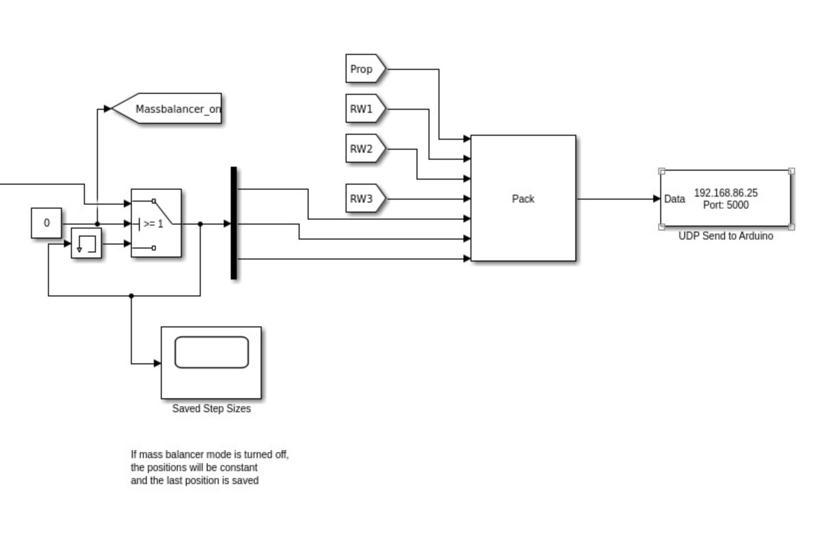
When the mass balancing algorithm is turned on, the propulsion systems will turn off and the stepper motors activate. When turned off, the positions are saved.
Additionally, each of the solenoids can be controlled for manual propulsion control. Otherwise, one of the automatic propulsion modes must be chosen (thruster, reaction wheel, or dual).
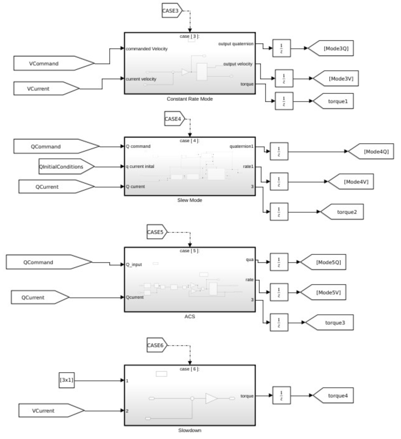
The inputs depend on the control mode (rate, quaternion, commands). They all output a target quaternion, rate, and torque.
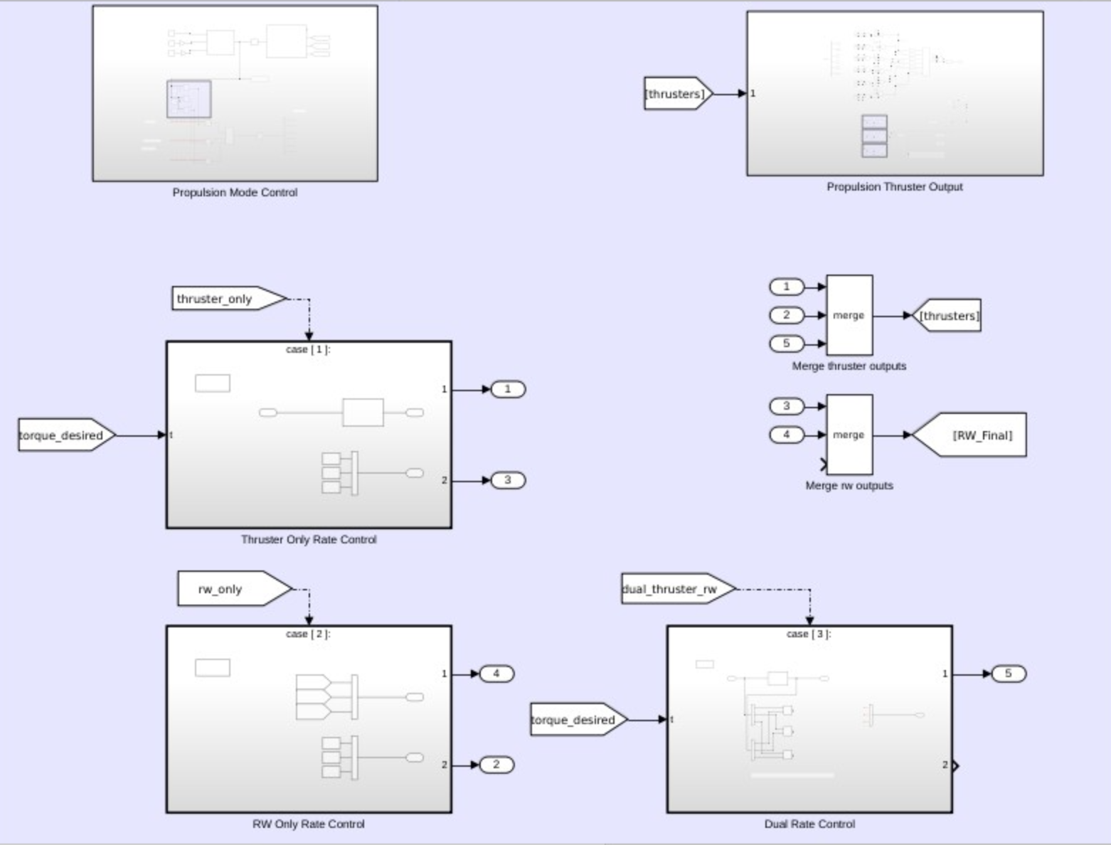
The Simulink structure of the propulsion integration is shown below, where the desired propulsion mode is activated by a case switch. Then, the propulsion values (binary values for the solenoids, and a speed for the reaction wheels) are calculated (using the desired torque as an input) and packaged. A MATLAB script calculates the best combination of thruster states by comparing the unit vectors of the desired torque versus the calculated torques output by the thrusters, and finding the best dot product.
Star Tracker and Kalman Filter
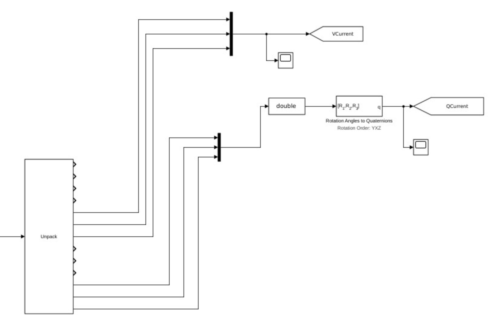
The on-board IMU provides accelerometer and gyroscope data, which is unpacked to determine the testbed's rate and quaternion at that state. However, relying on these sensors introduces error due to dead reckoning. Therefore, another measurement is provided by a star tracker (GoPro + Raspberry Pi), which takes a snapshot every ~1 second and compares to its map database to determine the quaternion.
Currently, an Extended Kalman Filter is being implemented within the Simulink model to take the IMU and star tracker data, and output a quaternion closer to reality. The IMU data at 33 hz is sampled much faster than the star tracker, but the algorithm must run at the slower 1 hz.