Lab 6: Orientation PID Control
Orientation PID with the IMU!
Prelab
First, to improve the sampling rate from Lab 5, I stored all the values into arrays and created a send_data function that loops through and sends them over Bluetooth. This significantly improved the performance of the PID control, running at ~100 hz and much faster than the sensor rate:
The send_data function is run at after PID control finishes if a send command flag is turned on (so the gains can more quickly be tuned without waiting for data from the previous trial to finish sending) or if Bluetooth is disconnected (to prevent loss of data).
void send_data() {
  for (int i = 0; i + 2 < tof_count; i += 3) {
    tx_estring_value.clear();
    tx_estring_value.append("T_TOF:");
    tx_estring_value.append(tofArray[i]);
    tx_estring_value.append("; Front Distance(mm):");
    tx_estring_value.append(tofArray[i + 1]);
    tx_estring_value.append("; Right Distance(mm):");
    tx_estring_value.append(tofArray[i + 2]);
    tx_estring_value.append(";");
    tx_characteristic_string.writeValue(tx_estring_value.c_str());
  }
  for (int i = 0; i + 3 < curIMU; i += 4) {
    tx_estring_value.clear();
    tx_estring_value.append("T_IMU:");
    tx_estring_value.append(gyroArray[i]);
    tx_estring_value.append("; ");
    tx_estring_value.append("Gyro:");
    tx_estring_value.append(gyroArray[i + 1]);
    tx_estring_value.append(", ");
    tx_estring_value.append(gyroArray[i + 2]);
    tx_estring_value.append(", ");
    tx_estring_value.append(gyroArray[i + 3]);
    tx_estring_value.append("; ");

    tx_characteristic_string.writeValue(tx_estring_value.c_str());
  }

  for (int i = 0; i + 4 < pwm_count; i += 5) {
    tx_estring_value.clear();

    tx_estring_value.append("T_PWM:");
    tx_estring_value.append(pwmArray[i]);
    tx_estring_value.append("; ");
    tx_estring_value.append("PWM value: ");
    tx_estring_value.append(pwmArray[i + 1]);
    tx_estring_value.append(";");
    tx_estring_value.append("Gains: ");
    tx_estring_value.append(pwmArray[i + 2]);
    tx_estring_value.append(" ");
    tx_estring_value.append(pwmArray[i + 3]);
    tx_estring_value.append(" ");
    tx_estring_value.append(pwmArray[i + 4]);

    tx_characteristic_string.writeValue(tx_estring_value.c_str());
  }
}
With this architecture, commands are easily sent while PID control is running, allowing us to change the distance setpoint and orientation for future labs.
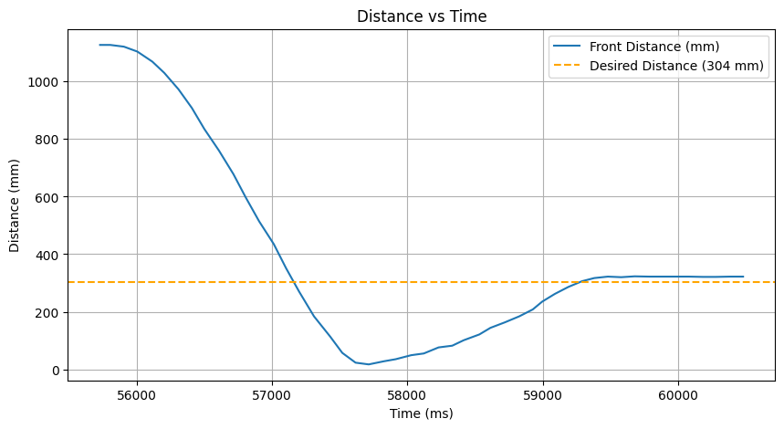
The PID values for linear control were retuned, and the control was much smoother:
Orientation Control
The goal of this lab is for the car to return to its original orientation after external disturbances.
Gyroscope Measurement
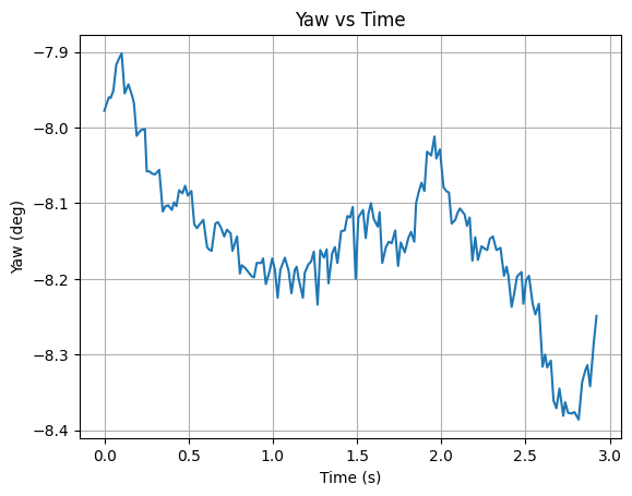
First, the yaw data was graphed. We observe that there is significant drift even while the car is still.
The onboard digital motion processor (DMP) was implemented to measure the orientation in quaternions and provide more accurate angle measurements.
Referencing the Example6_DMP_Quat9_Orientation script, the DMP was initialized in the setup function. Additionally, the ICM_20948_C.h class was edited to include #define ICM_20948_USE_DMP.
bool success = false;
while (!success) {
    success = true;
    success &= (myICM.initializeDMP() == ICM_20948_Stat_Ok);

    success &= (myICM.resetDMP() == ICM_20948_Stat_Ok);
    success &= (myICM.resetFIFO() == ICM_20948_Stat_Ok);

    success &= (myICM.enableFIFO() == ICM_20948_Stat_Ok);

    success &= (myICM.enableDMP() == ICM_20948_Stat_Ok);

    success &= (myICM.enableDMPSensor(INV_ICM20948_SENSOR_GAME_ROTATION_VECTOR) == ICM_20948_Stat_Ok);

    success &= (myICM.setDMPODRrate(DMP_ODR_Reg_Quat6, 0) == ICM_20948_Stat_Ok);
}
A function get_yaw was written to convert the quaternion measurements into yaw angles.
void get_yaw() {
    icm_20948_DMP_data_t dmp;
    myICM.readDMPdataFromFIFO(&dmp);

    if ((myICM.status != ICM_20948_Stat_Ok) && (myICM.status != ICM_20948_Stat_FIFOMoreDataAvail)) return;

    if ((dmp.header & DMP_header_bitmap_Quat6) <= 0) return;

    qx = ((double) dmp.Quat6.Data.Q1) / 1073741824.0;
    qy = ((double) dmp.Quat6.Data.Q2) / 1073741824.0;
    qz = ((double) dmp.Quat6.Data.Q3) / 1073741824.0;

    qw = sqrt(1.0 - min(((qx * qx) + (qy * qy) + (qz * qz)), 1.0));

    siny = 2.0 * (qw * qz + qx * qy);
    cosy = 1.0 - 2.0 * (qy * qy + qz * qz);
    gyro_yaw = (float)(atan2(siny, cosy) * 180.0 / PI);
}
Initially, the yaw values lagged behind and take a second to update due to the FIFO buffer filling with values between the initializing of the DMP and collecting values. The buffer was cleared when commanding COLLECT_PIDANGLE:
success = (myICM.resetFIFO() == ICM_20948_Stat_Ok);Now, there is much less drift, varying around +- 0.5 degrees while keeping the car still.
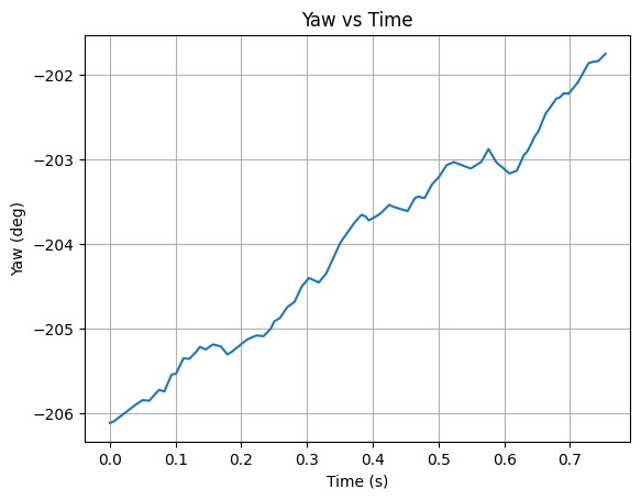
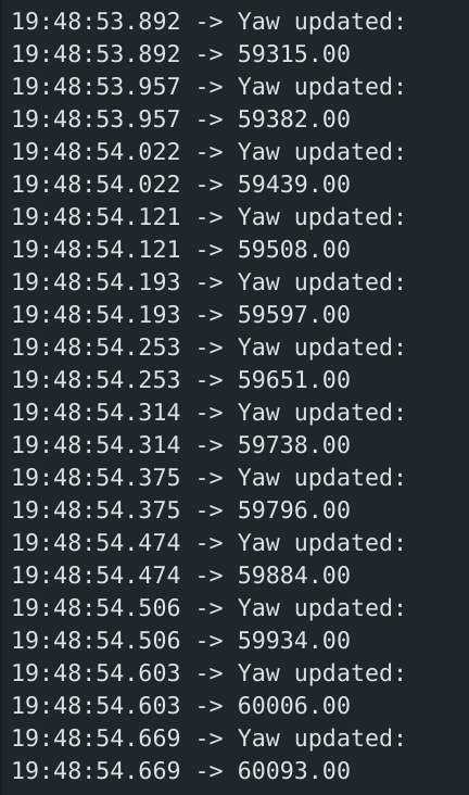
The real-time output of the yaw angle is shown below and appears to be extremely accurate and quick to update:
Gyroscope Limitations
The maximum rotational speed the gyroscope can read is 2000 degrees per second, or ~5.5 full rotations per second. Although this can be configured in the library's GYRO_CONFIG_1, the default value is sufficiently high for our purposes. The PID control and mapping will likely not require over 2 full rotations per second.
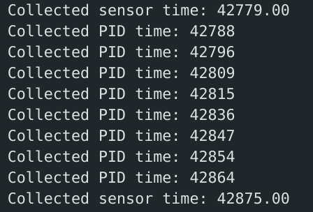
The sampling rate was tested with Serial print commands:
We observe that the gyroscope's sampling rate is around every ~65 ms, or ~15 hz. This is not ideal, as the angular PID control may be using old gyroscope data. For comparison, the linear PID control runs at ~100 hz as found in the Prelab.
PID Control
A CHANGE_SETPOINTS command was written to change the desired distance and angle over Bluetooth.
Overall, the angle PID structure was similar to that of the linear PID's flags and functions. Gain values for angular control (Kpa, Kia, and Kda) were initialized, and a function PID_angle_control was written to output PWM values with PID control.
Similarly to the linear control, the derivative term included a lowpass filter and eliminating the derivative kick. The yaw is based off of the quaternion measurements, so it is reasonable to take its derivative. Wind-up protection was implemented similar to Lab 5, constraining the integral PID component.
To prevent the car from rotating the long direction (for example, going from 1 to 359 degrees, we simply want to rotate -2 degrees), we map the dInput to [-180, 180] which represents the shortest path between two angles. The same is done for errorCur.
float last_filtered_d_angle = 0;
float filtered_d_angle = 0;
double lastInputAngle;

float PID_angle_control() {

  int t = millis();

  float tCur = micros() / 1000000.0;

  float angleCurrent = gyro_yaw;
  float errorCur = angleCurrent - angleWanted;

  if (errorCur > 180) errorCur -= 360;
  if (errorCur < -180) errorCur += 360;

  float dt = tCur - tPrev;
  if (dt <= 0) dt = 0.001;

  errorSum += errorCur * dt;
  errorSum = constrain(errorSum, -100, 100);

  errorDerivative = (errorCur - errorPrev) / dt;

  double dInput = angleCurrent - lastInputAngle;
  if (dInput > 180) dInput -= 360;
  if (dInput < -180) dInput += 360;
  lastInputAngle = angleCurrent;

  float d = -Kda * dInput;
  filtered_d_angle = dalphaa * d + (1 - dalphaa) * last_filtered_d_angle;
  last_filtered_d_angle = filtered_d_angle;

  float u = Kpa * errorCur + filtered_d_angle + Kia * errorSum;

  tPrev = tCur;
  errorPrev = errorCur;
}
Bluetooth commands the angular PID on/off. If turned off, the motors stop and the Arduino sends all its array data at once over Bluetooth. Although this results in some waiting, I found that the trade-off is worth it compared to the low frequency from real-time sending.
    case COLLECT_PIDANGLE:
      {
        int collect;

        success = robot_cmd.get_next_value(collect);
        if (!success)
          return;

        if (collect) {
          collectIMU = 1;
          collectPIDangle = 1;
          errorSum = 0;
          errorPrev = 0;

          tPrev = micros() / 1000000.0;

          bool success = 0;

          while (!success) {
            success = (myICM.resetFIFO() == ICM_20948_Stat_Ok);
          }

        } else {
          collectIMU = 0;
          collectPIDangle = 0;
          stop();
          if (send) {
            send_data();
          }
        }
      }
The main loop commands the car to turn left or right using those PWM values. I implemented a low angle tolerance of 1 degree.
      if (collectPIDangle) {
        pwm = PID_angle_control();
        get_PID();

        int pwm_max = 255 * Spa;

        int pwm_min = 100;
        int abs_pwm = abs(pwm) * pwm_max / 100;

        if (abs(errorCur) < pwm_angle_tolerance) {
          driveState = STOP;

        } else {

          if (abs_pwm > pwm_max) abs_pwm = pwm_max;
          if (abs_pwm < pwm_min) abs_pwm = pwm_min;

          if (pwm > 1) driveState = RIGHT;
          else if (pwm < -1) driveState = LEFT;
          else driveState = STOP;
        }

        switch (driveState) {
          case FORWARD: forward(abs_pwm); break;
          case BACK: back(abs_pwm); break;
          case LEFT: left(abs_pwm); break;
          case RIGHT: right(abs_pwm); break;
          case STOP: stop(); break;
        }
      }
While testing the stop function, I noticed that the right motor would have a delayed stop, around ~0.5 seconds after the left motor. Therefore, I implemented active braking:
void stop() {

  analogWrite(LEFT_1, 255);
  analogWrite(LEFT_2, 255);

  analogWrite(RIGHT_1, 255);
  analogWrite(RIGHT_2, 255);
}
Tuning and Results
A procedure similar to that of Lab 5 was followed and the following gains were chosen:
Kp = 0.06
Ki = 0.002
Kd = 0.05
Sp = 0.9
dalpha = 0.15
I first started with 0 Ki and Kd, and increased the Kp until the car started oscillating about an angle. To help eliminate steady state error, I slowly increased Ki until the system reached instability. I sent commands between 0 and 90 degrees to test wide turns. Kd was added to decrease disturbances, where I poked the side of the car.
To help the debugging process, graphs of the set desired angle, the measured angle, and the PWM values were created.
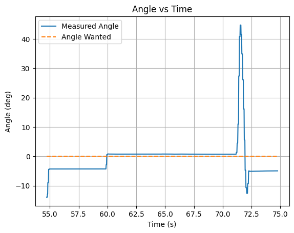
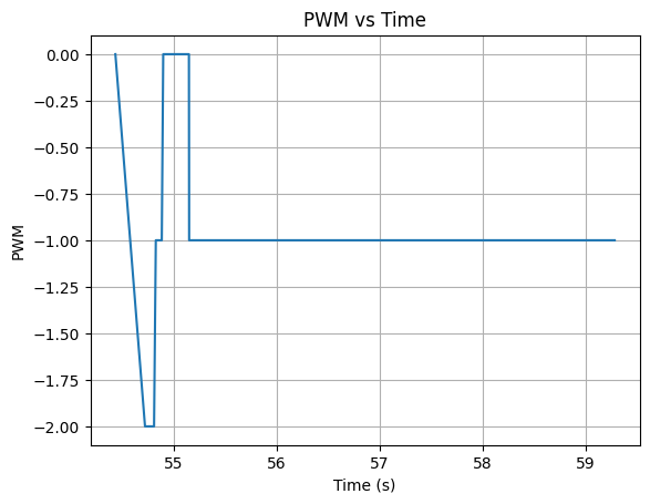
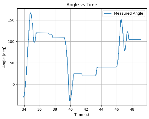
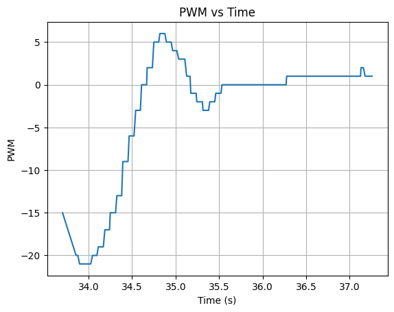
A successful trial and the resulting data is shown below, testing the angle commands with various sized jumps:
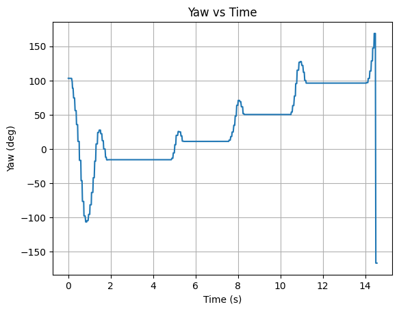
Note that the graph jumps when wrapping around from either the 180 or -180 end. Since this was a visual problem and does not affect the performance of the car, I decided to fix this in future labs.
Comparison without Wind-up Protection
The attempt below demonstrates the effect of the car without the wind-up protection:
The effects of overshoot are much more apparent as the integral term is no longer constrained. This is further shown in the PWM graph (which actually displays the PID control output u) with much higher values. Therefore, windup is necessary to prevent the car from spiraling out of control and spinning indefinitely with large overshoots.
Collaborations
Stephan's site was referenced for implementing the IMU digital motion processor and fixing the yaw drift.
ChatGPT was used for debugging the send_data function, notification handlers, and graphing data.