Lab 5: Linear PID Control
Position control into a wall, tuning PID gain values, and extrapolating ToF values.
Prelab
To help implement the PID controller, a proper debugging system was first set up.
A global flag collectPID is set on/off by the computer. When the flag is set to true, PID control and data collection begins. When the flag is set to false, the data collection stops and the car hard stops.
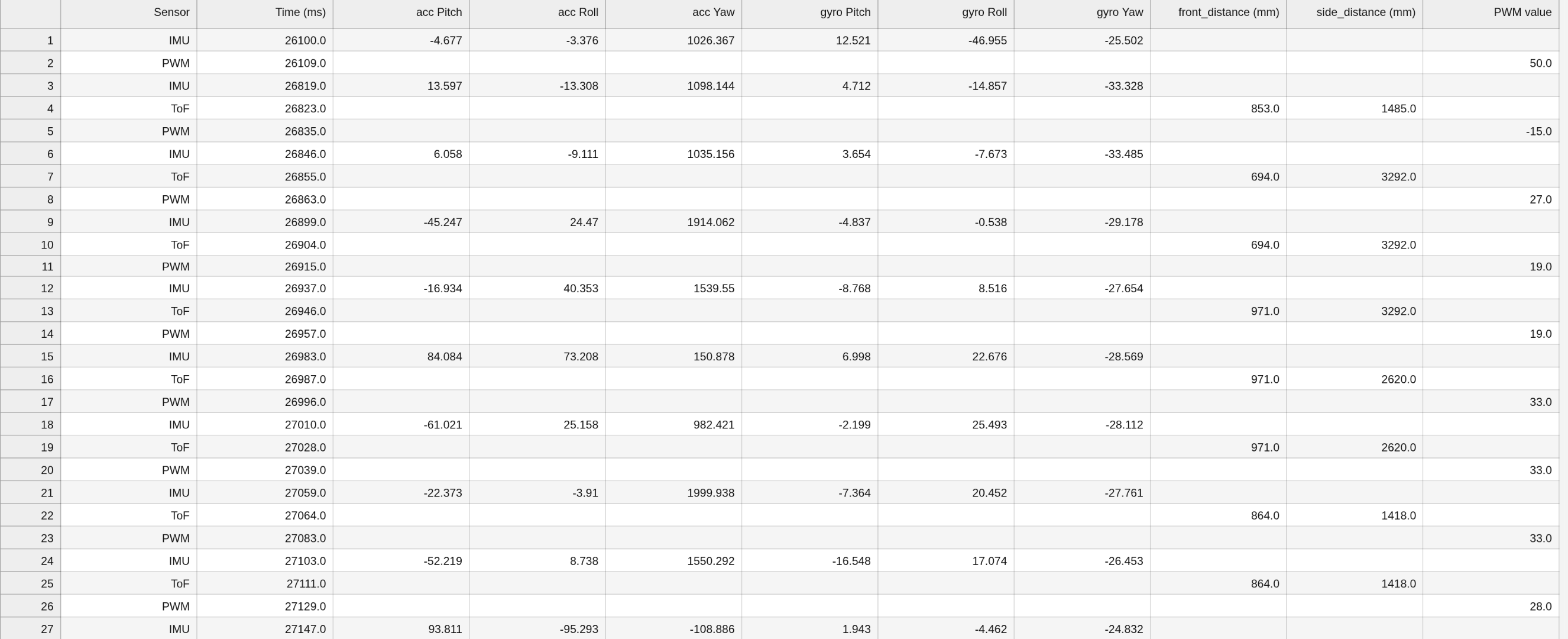
A notification handler is implemented to collect the debugging data into arrays. This data includes the timestamps, ToF and IMU sensor data, and the PWM values sent to the motors. An example of the logged data is shown below:
Additionally, the CHANGE_GAINS command was written for the computer to change the gain values, allowing the gain values to be frequently tweaked over Bluetooth without needing to reprogram the Artemis. This command's code was analogous to SEND_THREE_FLOATS in Lab 1. A speed factor Sp was also created to test different max speeds of the motor.
The DRIVE command was written to autonomously control the car's directions. Although this lab will only use the forward and back directions, the driveState value is still manipulated.
int driveState = 0;
#define STOP 0
#define FORWARD 1
#define BACK 2
#define LEFT 3
#define RIGHT 4
...
switch(driveState) {

    case FORWARD:
    forward(abs_pwm);
    break;

    case BACK:
    back(abs_pwm);
    break;

    case LEFT:
    left(abs_pwm);
    break;

    case RIGHT:
    right(abs_pwm);
    break;

    case STOP:
    stop();
    break;
}
A hard stop was implemented in the case that the Bluetooth central loop disconnects, all data collection and motors stop:
  stop(); // stop motors and sensors if Bluetooth disconnects
  collectIMU = 0;
  collectTOF = 0;
  collectPID = 0;
  distanceSensorFront.stopRanging();
  distanceSensorSide.stopRanging();
Position Control
The goal of this lab is to have the robot drive as fast as possible towards a wall and stop exactly 1ft (304mm) away. We use the following equation for full PID control:
$$ u(t) = K_p e(t) + K_i \int_0^t e(t) \ dt + K_d\frac{de(t)}{dt} $$
Proportional Control
First, only proportional control was implemented to make debugging easier.
We take u as a value 0-100 representing the percent of full speed the motors run at. Therefore, if an error of 2000mm corresponds to u = 100, then Kp is around 0.05. We use this as an initial guess before further tuning.
A function PID_control calculates and returns u:
float PID_control () {
    float tCur = micros()/1000000.0; // seconds

    float distanceCurrent = distanceFront;
    float errorCur = distanceCurrent - distanceWanted;

    float u = Kp*errorCur;
    tPrev = tCur;
    errorPrev = errorCur;

    return u;
}
Then, in the main loop, while collectPID is on, the u value is scaled into a PWM value, and a command is sent to the motors to run forward or backwards depending on the sign. The deadband is accounted for by setting the pwm value to the minimum value to overcome static friction if below. To ensure that the car stops at the target position, the pwm value is set to 0 if it falls within a set tolerance.
if (collectPID) {
int pwm_max = 255*Sp;
int pwm_min = 35;
int abs_pwm = 0;
tPrev = millis();
get_PID();
pwm = PID_control();
if (abs(pwm) < pwm_tolerance) {
abs_pwm = 0;
driveState = 0;
} else {
abs_pwm = abs(pwm) * pwm_max/100;
}
if (abs_pwm > pwm_max) {
abs_pwm = pwm_max;
} else if (abs_pwm > pwm_tolerance && abs_pwm < pwm_min) {
abs_pwm = pwm_min;
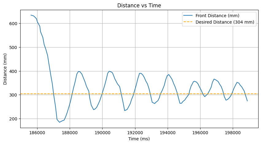
}The Kp value was increased until oscillation at 0.08.
Sensor Sampling Rate
From the ToF website, "...the maximum sampling rate for medium and long distance modes is 30 Hz". We want the sensor to have the highest sampling rate possible so that the PID control can use the most updated data and have the most accurate position control.
  distanceSensorFront.setTimingBudgetInMs(30);
  distanceSensorSide.setTimingBudgetInMs(30);
Extrapolation
To extrapolate ToF values based on recent sensor values, we first determine the frequency of ToF sensor data and PID control loop with Serial prints.
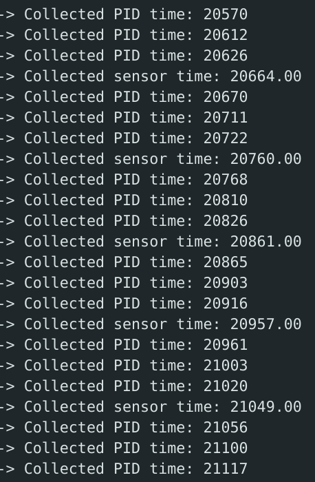
The collection of ToF sensor data and PID control are already decoupled since the main loop reads each flag separately. The PID control uses the latest value of distanceFront, even though the ToF is not updated as frequently. The PID control runs at ~30hz, and the ToF sensor runs at ~100hz. These speeds are slower than expected and may be due to Bluetooth sending.
To estimate ToF data to match the speed of the PID control, the past two data points are stored to get the slope and relate to the current point.
      if (collectTOF) {
        if (distanceSensorFront.checkForDataReady() && distanceSensorSide.checkForDataReady()) {
          get_TOF();
        } else if (tof_count > 3) {  // extrapolation
          float slope = (distanceFront - last_distanceFront) / (t - last_ttof);

          float t_pid = millis();

          float dt = (t_pid - ttof)/1000.0;

          distanceFront = slope * dt  + distanceFront;
          tx_estring_value.clear();
          tx_estring_value.append("Extrapolated:");
          tx_estring_value.append(t);
          tx_estring_value.append(";");
          tx_estring_value.append(distanceFront);
          tx_characteristic_string.writeValue(tx_estring_value.c_str());
        }
      }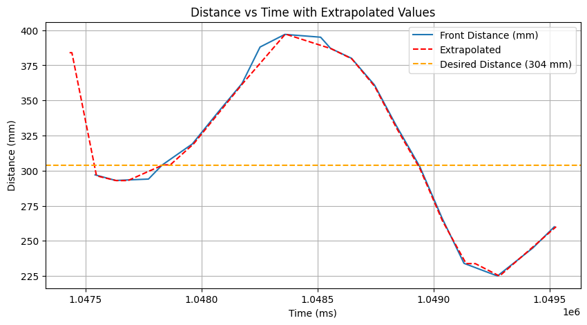
By comparing the raw and extrapolated data, we observe that the extrapolated values are not updated as frequently as the raw values since it already runs relatively slowly. It somewhat smoothens out the flat raw values. To improve performance and sampling rate, messages could be first stored in arrays, and then iterated and sent over Bluetooth.
Derivative Control
Next, derivative control was implemented by adding to the PID_control function:
  errorDerivative = (errorCur - errorPrev) / dt;
...
  float u = Kp*errorCur + Kd*errorDerivative
By plotting the car's motion, I decided it would be necessary to include a low pass filter and eliminate the kick due to the rapid, jittery motions.
For the low pass filter, I added a dalpha that could be changed through Bluetooth. To eliminate the kick, I replaced the derivative of the error to the last input.
  void PID_control(){
    ...
  double dInput = Input - lastInput;
  lastInput = Input;

  float d = -Kd * dInput;
  filtered_d = dalpha * d + (1 - dalpha) * last_filtered_d;
  last_filtered_d = filtered_d;

  float u = Kp * errorCur + filtered_d;
  ...
  }
For the example below, alpha = 0.75, Kp = 0.05, and Kd = 0.1.
Integrator Control
The last element to add to the PID_control is the integrator.
...
errorSum += errorCur * dt;
float windup = constrain(Ki*errorSum, -200, 200);
float u = Kp * errorCur + filtered_d + windup;
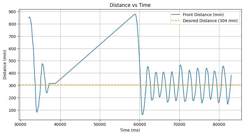
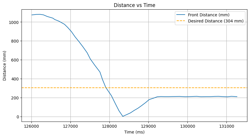
...To prevent wind-up error, where the integral term keeps growing without limit, the term is constrained. To demonstrate the difference with and without wind-up protection, the robot is started far from the wall to accumulate error.
Without wind-up protection:
With wind-up protection:
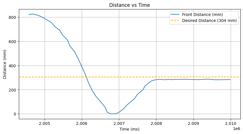
We observe that the windup protection prevents the car from accelerating sharply into the wall and reduces the steady state error.
Tuning and Results
The heuristic process from lecture was followed to tune the gains:
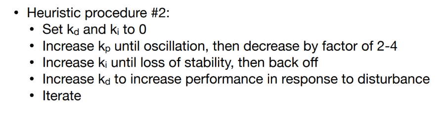
The final values were selected:
Kp = 0.05
Ki = 0.001
Kd = 0.12
Sp = 0.5
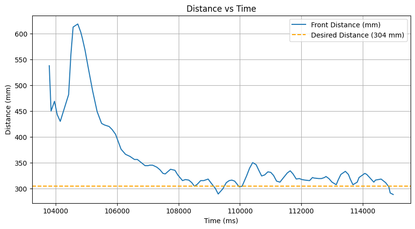
dalpha = 0.15Three successful trials are shown below, tested ~1m from the wall:
Additionally, the car settles into the desired position after external disturbances:
The maximum linear speed acheived, calculated by the front ToF sensor, was determined to be around 0.48 m/s.
To improve the position control's overshoot, steady state error, maximum speed, and maximum distance from the wall, is essential to increase the sampling rate of the PID_control and sensors, as well as to test the car on non-carpeted floor.
Collaborations
Stephan's site was referenced for initial gain values, PID control setup, the idea of adding a speed factor, and wind-up protection.
Brett's site was referenced for implementing the derivative kick.
ChatGPT was used for notification handling, plotting, finding the maximum linear speed, and debugging the extrapolation algorithm.