Lab 4: Motors and Open Loop Control
Driving the motors with dual motor drivers, more wiring and soldering, and testing open loop commands.
Prelab
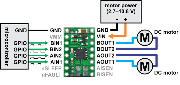
The documentation for the dual motor drivers show the wiring to the motors and Artemis, though we will parallel-couple the inputs and outputs to each motor.
To choose which pins to control on the Artemis, we look at the datasheet for ~ alternating current pins:
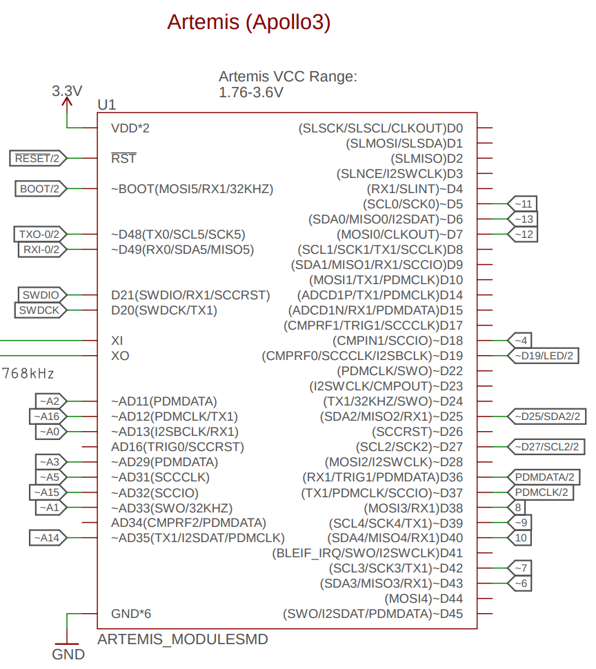
I decided on pins A2, A3, A14, and A15 due to their location, separating the dual motor drivers.
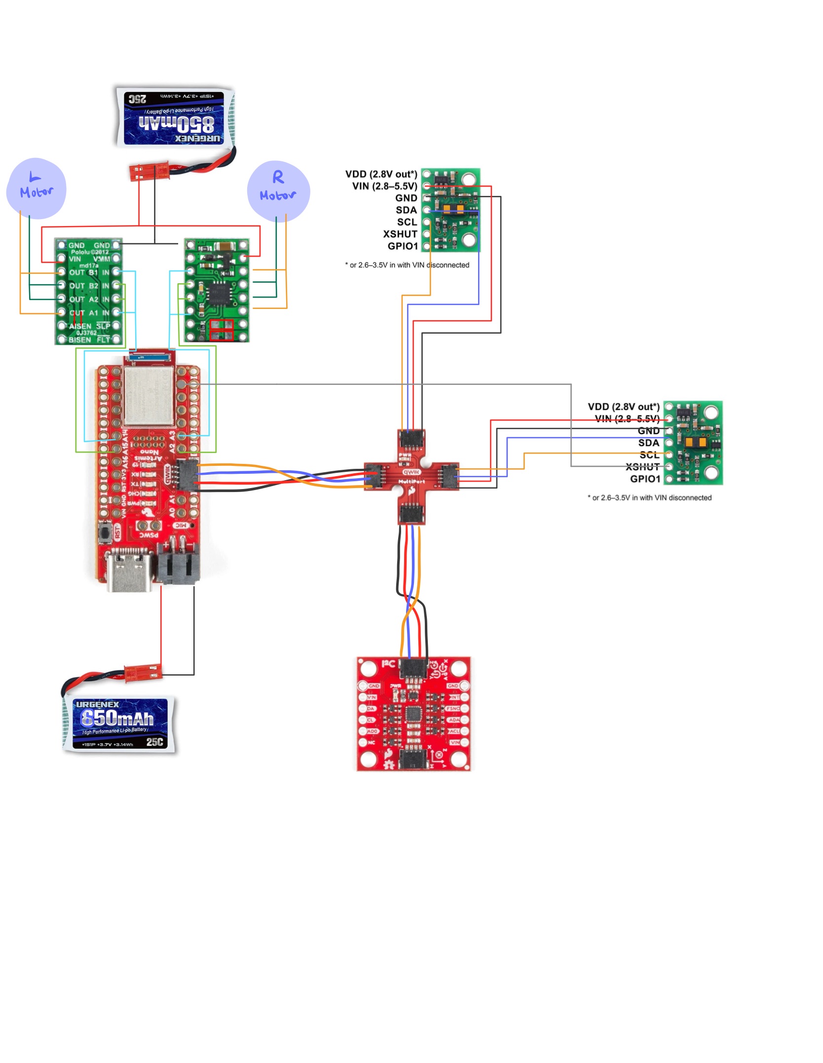
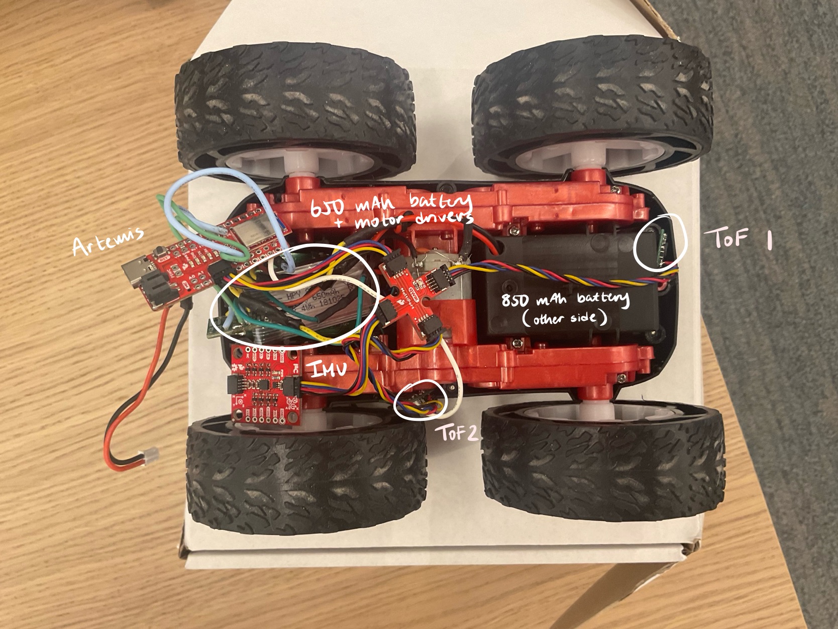
The Artemis and motors are powered with separate batteries for higher battery capacity and to prevent the high power draw from the motors interfering with the Artemis.
The complete wiring diagram with the added motors and motor drivers is shown below:
Installing Dual Motor Drivers
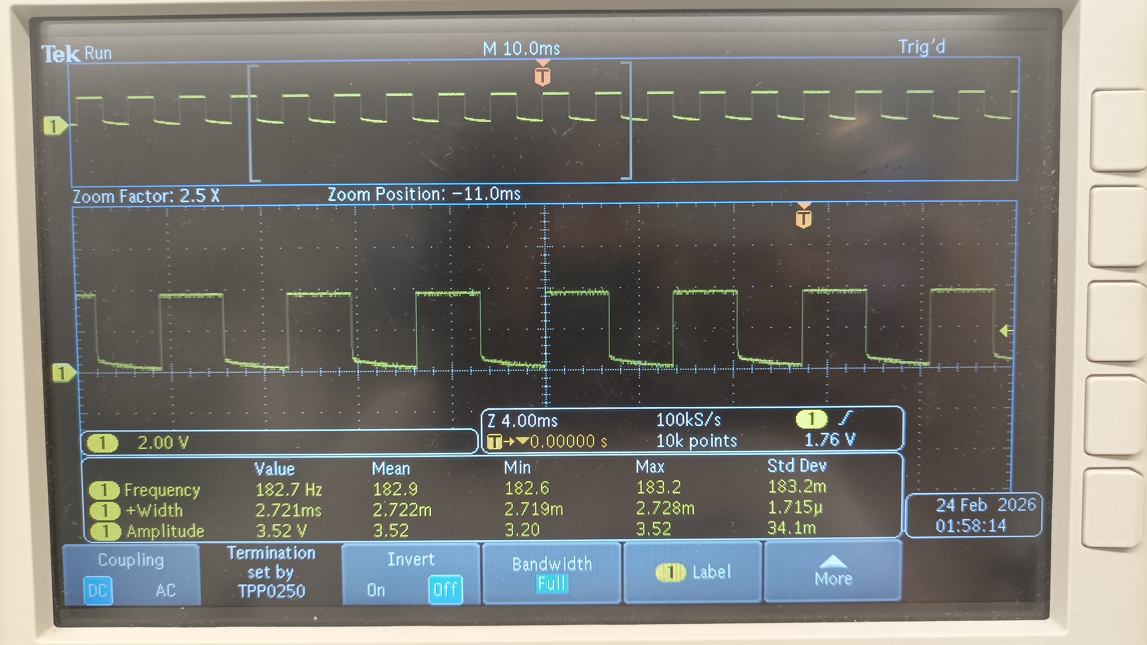
One of the dual motor drivers was first tested. The dual motor driver IN pins were soldered to the Artemis pins, the VIN and GND connected to the external power supply, and the the OUT pins were soldered together and connected to the oscilloscope.
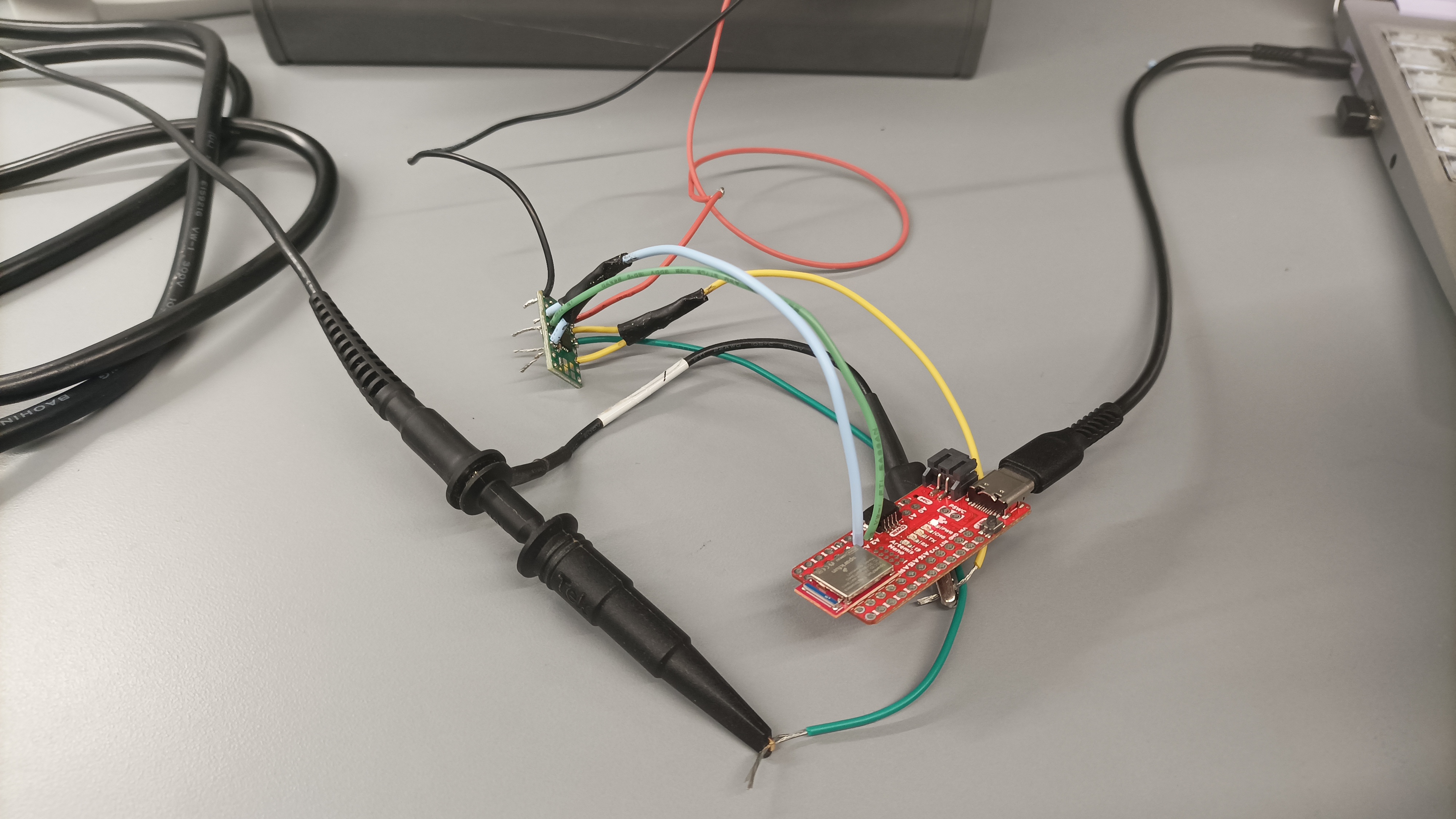
The power supply is set to 3.7V, the rating for the 850 mAh battery. We confirm that the motor driver operates with a constant supply.
The power can be regulated on the motor driver output with analogWrite commands, in which the signals display on the oscilloscope.
#define LEFT_1 A14
#define LEFT_2 A15

#define RIGHT_1 A2
#define RIGHT_2 A3

void setup() {

}

void loop() {

  analogWrite(LEFT_1, 127);
  analogWrite(LEFT_2, 0);

  analogWrite(RIGHT_1, 127);
  analogWrite(RIGHT_2, 0);

}
We confirm that the car operates with the 850mAh battery.
Finally, the second dual motor driver is soldered and connected. All components were installed into the car.
PWM Limits and Calibration
First, the lower limit PWM values were tested experimentally. I determined that the minimum values to overcome friction were 35 for moving forward and 95 for turning in either direction. We observe that the static friction in turning is much greater than that in driving forward.
Next, the left and right motors were calibrated for the car to move in a straight line. I experimentally determined that the left motor's PWM values must be 1.12 times greater than the right motor.
#define LEFT_1 A14
#define LEFT_2 A15

#define RIGHT_1 A2
#define RIGHT_2 A3

float calibration = 1.12;

void forward(){
int pwm = 70;
  analogWrite(LEFT_1, round(pwm*calibration));
  analogWrite(LEFT_2, 0);

  analogWrite(RIGHT_1, pwm);
  analogWrite(RIGHT_2, 0);
}

void stop() {
  analogWrite(LEFT_1, 0);
  analogWrite(LEFT_2, 0);

  analogWrite(RIGHT_1, 0);
  analogWrite(RIGHT_2, 0);
}

void left(){
  int pwm = 95;
  analogWrite(LEFT_1, round(pwm*calibration));
  analogWrite(LEFT_2, 0);

  analogWrite(RIGHT_1, 0);
  analogWrite(RIGHT_2, pwm);

}

void right(){
  int pwm = 95;
  analogWrite(LEFT_1, 0);
  analogWrite(LEFT_2, round(pwm*turn_calibration));

  analogWrite(RIGHT_1, pwm);
  analogWrite(RIGHT_2, 0);
}

void setup() {
  forward();
  delay(3000);
  stop();
}
The car successfully drove straight for ~10 ft. However, it starts to veer right at the end as the wheels slow down at different rates.
Open Loop Control
Commands were looped to allow the car to autonomously move forward, turn left or right, and stop.
void loop() {

  forward();
  delay(2000);

  left();
  delay(3000);

  stop();
  delay(1000);

  right();
  delay(2000);
}
Additional Tasks
PWM Frequency
To determine the frequency at which analogWrite generates, the time at each loop was printed to Serial.
void loop() {
  int t;
  t = micros();
  Serial.println(t);

  analogWrite(LEFT_1, 127);
  analogWrite(LEFT_2, 0);
  analogWrite(RIGHT_1, 127);
  analogWrite(RIGHT_2, 0);
}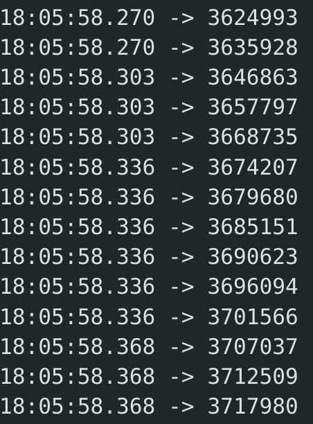
It takes ~5000 microseconds for 4 analogWrite commands, or a 800 hz frequency for each analogWrite, which is adequately fast in comparison with the frequency for the IMU and ToF sensors.
Manually configuring the timers to generate a faster PWM signal would improve motor control precision, as it can switch speeds closer to an instantaneous rate. Additionally, noise would be reduced, leading to smoother control.
Absolute Lowest PWM
To determine the lowest PWM values that the car can run at after overcoming static friction, new commands were written to first set the PWM value slightly above the minimum and then switch to a lower value, signified with the LED on. I experimentally determined the absolute lower PWM values for moving forward and turning to be 30 and 90, respectively.
void settle_forward() {
  int pwm = 50;
  int settle = 30;

  analogWrite(LEFT_1, pwm*calibration);
  analogWrite(LEFT_2, 0);
  analogWrite(RIGHT_1, pwm);
  analogWrite(RIGHT_2, 0);

  delay(2000);

  digitalWrite(LED_BUILTIN, HIGH);

  analogWrite(LEFT_1, settle*calibration);
  analogWrite(LEFT_2, 0);
  analogWrite(RIGHT_1, settle);
  analogWrite(RIGHT_2, 0);

  delay(7000);

  digitalWrite(LED_BUILTIN, LOW);
}

void settle_turn() {
  int pwm = 120;
  int settle = 90;

  analogWrite(LEFT_1, pwm*calibration);
  analogWrite(LEFT_2, 0);
  analogWrite(RIGHT_1, 0);
  analogWrite(RIGHT_2, pwm);

  delay(2000);

  digitalWrite(LED_BUILTIN, HIGH);

  analogWrite(LEFT_1, settle*calibration);
  analogWrite(LEFT_2, 0);
  analogWrite(RIGHT_1, 0);
  analogWrite(RIGHT_2, settle);

  delay(8000);

  digitalWrite(LED_BUILTIN, LOW);
}
As shown in the videos below, once the car switches to the lower PWM value and the LED turns on, it takes ~2 seconds for the car to settle at the slowest speed.
Collaborations
Wenyi's wiring diagram was referenced.